


Feature Story
More feature stories by year:
2024
2023
2022
2021
2020
2019
2018
2017
2016
2015
2014
2013
2012
2011
2010
2009
2008
2007
2006
2005
2004
2003
2002
2001
2000
1999
1998
![]() Return to: 2014 Feature Stories
Return to: 2014 Feature Stories
CLIENT: IMAGINATION TECHNOLOGIES
Apr. 2, 2014: Computing Now
By Peter McGuinness, Imagination Technologies
The concept of ray tracing has been bandied about for more than a generation – since 1968, it has been viewed as a promising technology, especially for visual arts disciplines, and in particular, the entertainment industry.
Why? Because the ray tracing algorithm as developed into its recursive form can closely model the behavior of light in the real world so that shadows, reflections and indirect illumination are available to the artist without any special effort.
These effects, which we take for granted in life, are available only with a great deal of explicit effort in a scanline rendering environment so a practical, economical way of generating them implicitly in real time is highly desirable.
Unfortunately, the computational and system cost of all implementations to date has meant that ray tracing to date has been mostly limited to offline rendering or very high cost, high power systems which can be real time but lacks the element of interactivity. In fact, the wait for practical ray tracing has been so long that at last year's influential Siggraph conference in Anaheim, the headline session on raytracing was wryly entitled: "Ray tracing is the future and ever will be".
Fast forward 46 years. Today, there's now a novel, comprehensive approach to real time, interactive ray tracing which addresses these issues and proposes a scalable, cost efficient solution appropriate for a range of application segments including games consoles and mobile consumer devices.
The process is simple: once the model is transformed into world space (the 3D coordinate system used for animation and manipulation of models) and a viewport has been defined, a ray is traced from the camera through each pixel position in the viewport into the volume occupied by the model and intersected with the closest object. This primary ray determines the visibility of objects from the perspective of the camera. Assuming an intersection is found, three or more new rays are generated: reflection, refraction if appropriate, and one illumination ray for each light source.
These secondary rays are then traced, intersected and new rays generated until a light source is intersected or some other limit is reached. At each bounce, a color contribution to the surface is computed and added into an accumulation buffer; when all rays are resolved the buffer contains the final image.
Once the model is created, the material properties defined and the lights placed, all of the lighting effects occur automatically during the rendering process.
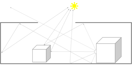
Figure 1 Ray Tracing models the transport of light in a scene.
This is in contrast to the process of creating realistic per-pixel lighting effects in a scanline renderer: in this case, since the world space model is discarded before fragment rendering begins, all the lighting effects must be captured during the content creation process and 'baked in' to special purpose textures known as light maps, which can then be used to layer the pre-computed lighting values onto the surface of the objects.
While it is possible in principle to generate light maps dynamically as an inline pre-processing step and implementations exist which do that, real time applications generally adopt the pre-baking approach in order to reserve available horsepower for other rendering effects. Shadows for example, which must be computed dynamically in an interactive system, are handled by techniques which involve multiple passes over the scene geometry at run time in order to generate shadow maps, which, similar to the light maps, are applied during the final rendering pass.
Aside from the computational expense of this approach, it has numerous disadvantages due to the need to predict which maps will be needed and to carry them as game assets, constraining interactivity and increasing the size of the data set needed to run the application. In addition to these problems, the maps are generated with a limited number of fixed resolutions, which poses the usual resolution problems associated with image based techniques.
The general acceptance of ray tracing as a desirable technique is illustrated by its use alongside a number of ray tracing-like techniques in the offline light map baking process used in today's content generation middleware packages. These are used to generate the input images for light map baking and point the way to an incremental method of introducing ray tracing into existing real time rendering systems, such as OpenGL and DirectX, without abandoning the overall structure of those systems. This is obviously desirable since the use of existing tools and runtimes as well as all of the sophisticated techniques already known to developers can then be preserved and enhanced, providing a low-impact migration path to the newer techniques.

Figure 2 An image created by Mads Drøschler using PowerVR Ray Tracing technology
This is accomplished by adding the capability to the shading language used by the runtime engine to allow any shader program to cast rays during its execution. The rendering pipeline is not changed, it is still an immediate, incremental, scanline method of rendering; existing methods of primary visibility determination are retained but the rendering system is enhanced with a retained data structure and a method to resolve ray queries into it.
Once this capability is available, and with sufficient runtime performance, the pre-baking method can be abandoned, with the result that the workflow of application development is simplified while at the same time the visual quality and dynamism of the end result are significantly enhanced. The problems to date have been that adequate runtime performance has been lacking or too expensive and interactivity has been very limited; in particular, attempts to map ray tracing onto existing GPU hardware have run into serious problems of efficiency.
The main difficulty comes from the fact that current real time rendering systems exploit screen space data locality to achieve performance through parallelization. The data associated with any task being worked on is coherent both in the sense that adjacent pixels in a triangle reside close together in memory and also in that they tend to share material properties so that access to textures, shader programs etc. is efficient and amenable to parallelization. This is not the case with a ray traced system, where visually-adjacent objects can be widely separated in the world space coordinate system and where rays typically become widely divergent with successive bounces. So while the GPU-centered method works, it is extremely inefficient to the point of impracticality.
There are two further problems related to the retained data structure: building and traversal. Interactive animation requires that the acceleration structure (typically a voxelized tree) must be updated in real time and current methods of updating are both slow and unpredictably expensive. Likewise, a lightweight method of traversal is needed which minimizes data fetches from the acceleration structure; the following sections propose solutions for all three of these problems and describe the Imagination Technologies IP core implementation based on them.
Since the objective is to add ray tracing capability to a standard GPU, it is useful to discuss the basic organization of that unit. Variations exist, especially in low level details but in general GPU shader units are organized into SIMD (Single Instruction, Multiple Data) arrays of ALUs (Arithmetic Logic Unit) into which tasks – groups of operations – are dispatched by schedulers for execution. The operations, called instances in the PowerVR architecture, are chosen to maximize the extent to which they share coherency characteristics such as spatial locality, material properties, etc. in order to maximize the efficiency of fetching their attribute data from memory as well as the parallelism of their execution across wide SIMD arrays. In the PowerVR architecture, the arrays are grouped into Unified Shading Clusters (USCs). The process of scanline rendering naturally results in a high degree of this type of coherence, so the arrays can be kept busy, with ALU latencies and the inevitable memory access latencies masked to a certain degree by task switching. There are a number of data masters feeding into the schedulers to handle vertex related, pixel related and compute related tasks and once the shading operation is done, the result is output into a data sink for further processing, depending on what part of the rendering pipeline is being handled.

Figure 3 GR6500 Block Diagram
The ray tracing unit (RTU) can be added to this list as both a data sink and a data master so that it can both receive (sink) new ray queries from the shaders and dispatch (master) ray/triangle intersection results back for shading. It contains registers for a large number of complete ray queries (with user data) attached to a SIMD array of fixed-function "Axis Aligned Bounding Box vs. Ray" testers and "Triangle vs. Ray" testers.
Importantly, there is a coherence gathering unit which assembles memory access requests into one of two types of coherency queues: intersection queues and shading queues, then schedules them for processing. Intersection queues are scheduled on to the SIMD AABB or triangle testers; shading queues are mastered out to the USCs.
Intersection queues are created and destroyed on the fly and represent a list of sibling Bounding Volume Hierarchy (BVH) nodes or triangles to be streamed in from off-chip memory. Initially the queues are typically full naturally because the root BVH nodes span a large volume in the scene and therefore most rays hit them consistently. When a full queue of rays is to be tested against the root of the hierarchy, the root nodes are read from memory and the hardware can intersect rays against nodes and/or triangles as appropriate.
For each node that hits, a new intersection queue is dynamically created and rays which hit that node are placed into the new child queue. If the child queue is completely full (which is common at the top of the BVH), it is pushed onto a ready stack and processed immediately. If the queue is not full (which occurs a little deeper in the tree, especially with scattered input rays from the USC), it is retained in a queue cache until more hits occur against that same BVH node at a later time. In this mode, the queues effectively represent an address in DRAM to start reading in the future. This has the effect of coherence gathering rays into regions of 3D space and will dynamically spend the queues on areas of the scene which are more challenging to collect coherence against.
This process continues in a streaming fashion until the ray traverses to the triangle leaf nodes; when a ray is no longer a member of any intersection queue, the closest triangle has been found.
At this point, a new shading queue is created, but this time it is coherence gathering on the shading state that is associated with that triangle. Once a shading queue is full, this becomes a task which is then scheduled for shader execution. Uniforms and texturing state are loaded into the common store and parallel execution of the shading task begins: each ray hit result represents a shading instance within that task.
The behavior is then identical to that of a rasterization fragment shader with the added feature that shaders can create new rays using a new instruction added to the PowerVR shader instruction set, and send them as new ray queries to the RTU.
The RTU returns ray/triangle intersection results to the shaders in a totally different order than that which they entered due to the coherence gathering. A ray which enters the RTU early in the rendering of a frame may be the last to leave depending on coherence conditions.
This approach to dynamic coherence gathering has the effect of parallelizing on rays instead of pixels which means that even rays which originate from totally different ray trees from other pixels can be collected together to maximize all available coherence that exists in the scene. This then decouples the pipelines, creating a highly latency tolerant system and enabling a very extensive set of reordering possibilities.
In order for this approach to be effective, a critical mass of in-flight rays needs to be maintained in fast on-chip SRAM. A non-blocking ray tracing model is employed by the design which allows the amount of state that can be carried with any ray to be carefully bound.
Take as an example a typical depth first ray tracing shader that would cast a ray in order to determine the color of the object that ray intersects; since this can occur recursively, a large stack of shader states can build up for every ray making it impractical to get enough rays in flight to coherence gather effectively and fit within precious on-chip memory.
In the non-blocking model, the shader creates the ray, writes all the information needed to resolve that ray later and then emits the ray into the RTU and completes without waiting for the result.
When the ray then executes a shader at some point in the future (non-deterministic due to the coherence gathering going on in RTU), it knows the pixel it is contributing to and the contribution of the ray due to the color information that was passed along. This can continue recursively down the ray-tree and shaders are free to cast multiple rays per shade. The key is that all the emitted rays within the originating pixel will accumulate back into the pixel with various contribution factors which are modulated by the various shaders that are hit as the rays bounce around.
The accumulates occur in an on-chip 'Frame Buffer Accumulator' (FBA) memory, which caches pixels on chip and effectively acts as an atomic ReadModifyWrite floating point adder for those pixels. A successful implementation of a production renderer using this non-blocking approach found that there are only a small number of behaviors that can't be quite easily mapped into this model
The final element is building of the acceleration structure which must be a fully dynamic system capable of augmenting a rasterizer. This is done in a 'Scene Hierarchy Generator' (SHG) which implements an algorithm to build the BVH for the RTU in a streaming fashion and is placed directly after the vertex shader. The SHG builds the AABB hierarchy in a bottom up fashion and writes it directly into DRAM.
Internally, the SHG treats the entire world as a log2 sparse oct-tree. It has a core concept of a spatial node which is effectively an integer address within the log2 oct- tree, i.e. [xyz] and "Level" (which is effectively the log2 size of the voxels at that level). These integral representations of 3D space are re-linked rapidly in a small on- chip SRAM but never actually leave the chip until they are properly arranged and are then streamed out as AABB BVH nodes.
The SHG reads each input triangle from the vertex shader exactly one time and writes out AABBs into DRAM in a streaming manner, starting at the bottom of the tree and building up. The SHG algorithm makes two key assumptions that allow for this favorable behavior:
Using the first assumption, the SHG compares the size of each incoming triangle against the overall scene size to determine at which log2 level to voxelize the triangle. Big triangles have lower log2 levels and are higher in the tree; small triangles go deeper. Furthermore, "long and skinny" triangles that are off-axis are pushed deeper so as to get more fine grain voxelization and therefore more efficient bounding by the AABBs that will later result.
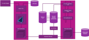
Figure 4 Single pass construction of the acceleration data structure.
The voxelizers produce nodes for the triangles which are fed through a 3D voxel cache. This cache effectively determines the spatial grouping of triangles - when the cache has a hash collision or is flushed, nodes are generated. (This 3D caching scheme is built on the 2nd assumption mentioned above and in practice works very well.)
These nodes then in turn have a parent node address computed and are fed again through a voxel cache. The algorithm works its way up the tree, writing out grouped AABBs into DRAM ready for the RTU.
From a graphical developer's perspective, the barrier to using ray tracing is lowest if it is possible to retain all of the currently used development flow, including tools and APIs. This means that, rather than switch wholesale to a new rendering scheme (such as the primary ray method of visibility determination described above) it is desirable to create a hybrid system where an incremental scanline algorithm is used for visibility determination but ray tracing can be selectively added in order to implement specific effects.
A graphical API such as OpenGL does not have the primary ray concept used to determine visibility in a pure ray tracing renderer; this function is performed by the scanline rasterization algorithm which takes place in the screen space coordinate system whereas rays must be cast in world space. One way to resolve this issue is to make use of a multipass rendering technique known as deferred shading.
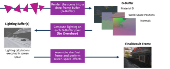
Figure 5 A Modern Game Engine using deferred shading.
This technique is commonly used in game engine runtimes and consists of a first, geometry, pass which performs the visibility determination followed by a second, shading, pass which executes the shader programs attached to the visible geometry. The objective of this technique is to reduce the overhead of shading objects which are invisible but it can also be used to cast the starting rays in a hybrid system. Since the intermediate information stored after the first pass includes world space coordinates as well as things like surface normals, the shader program has everything needed to cast the first rays.

Figure 6 Hybrid Rendering in a Game Engine leveraging the deferred shading G-Buffer
This method benefits from the fact that only visible pixels will cast rays but it also means that the developer has the choice of casting rays only for selected objects and can therefore easily control how effects are used and where the ray budget is spent. It can also be very easily fitted into existing game engine runtimes so that workflow remains the same and investment in all existing game assets is preserved. This level of control means it is possible to progressively move assets from incremental techniques to ray tracing techniques, giving the developer the flexibility needed to successfully manage that transition.

Figure 7 Traditional, rasterized-only rendering cannot easily model light transport accurately

Figure 8 PowerVR Ray Tracing GPUs offer ultra-realistic shadows, reflections and transparency at no extra cost
The most obvious use of ray tracing in a game is to implement fully dynamic lights with shadowing and reflections generated at runtime. The improvements in realism and interactivity which this makes possible include shadows and reflections which are free of sampling artefacts and the ability to remove constraints on freedom of movement of the player. This enhanced freedom of movement is an enabling technology for applications such as virtual and augmented reality and opens up whole new applications in areas such as online shopping.
In addition, the developer can now access a broad range of other capabilities that would either be impossible, low quality or too inefficient using standard techniques.
Some examples of these include:
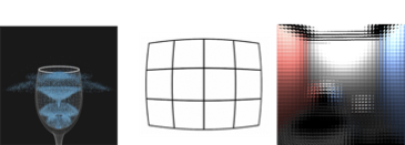
Figure 9 Physics, Lens distortion correction and lenticular display rendering can be implemented using RayTracing
The hardware ray tracing solution described here is available today for silicon implementation in a cost and power profile suitable for handheld and mobile devices (today's dominant platforms for games as well as other consumer-centric activities).
The performance and features it offers along with a low risk, migration path is very compelling to developers who want to simplify their content creation flow at the same time as creating more compelling, more realistic games. As this technology is rolled out over the coming months, it will soon be possible to say that the promise of ray tracing is being fulfilled: the future will finally have arrived.
Editor's Note: Peter McGuinness is Director of Multimedia Technology Marketing for Imagination Technologies Group plc (LSE:IMG; www.imgtec.com). Imagination Technologies - a global leader in multimedia, processor, communication and cloud technologies - creates and licenses market-leading processor solutions including graphics, video, vision, CPU and embedded processing, multi-standard communications, cross-platform V.VoIP and VoLTE, and cloud connectivity. Contact Mr. McGuinness at peter.mcguinness@imgtec.com.
Return to: 2014 Feature Stories